
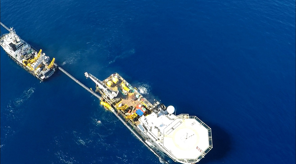
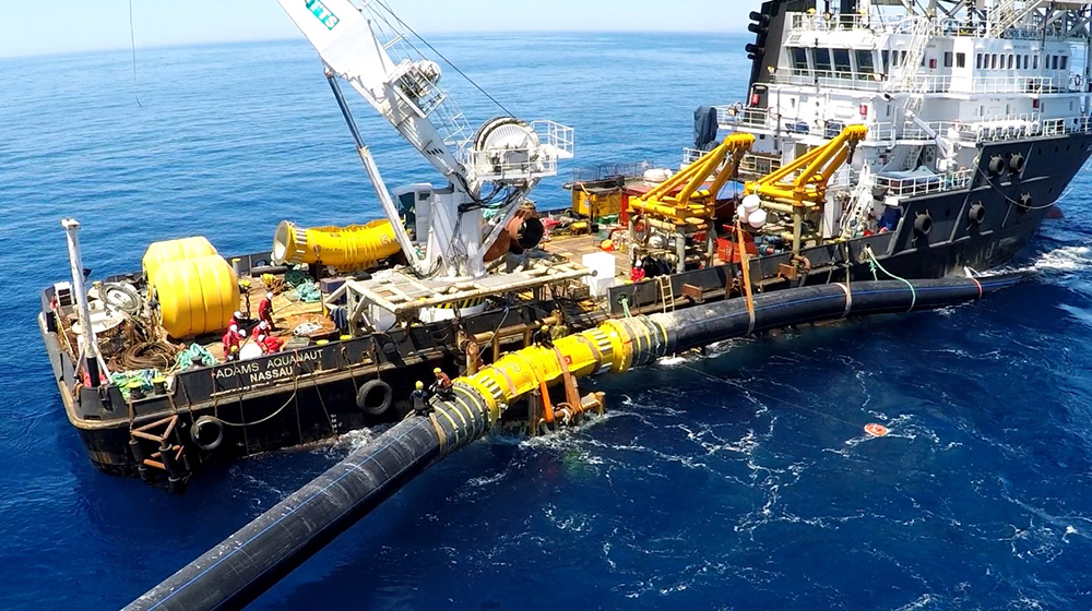
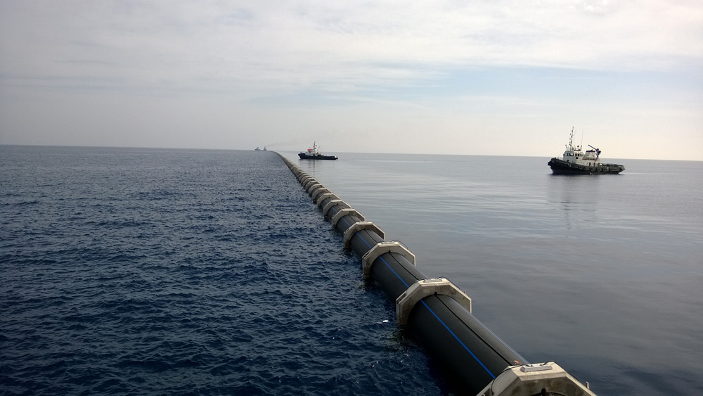


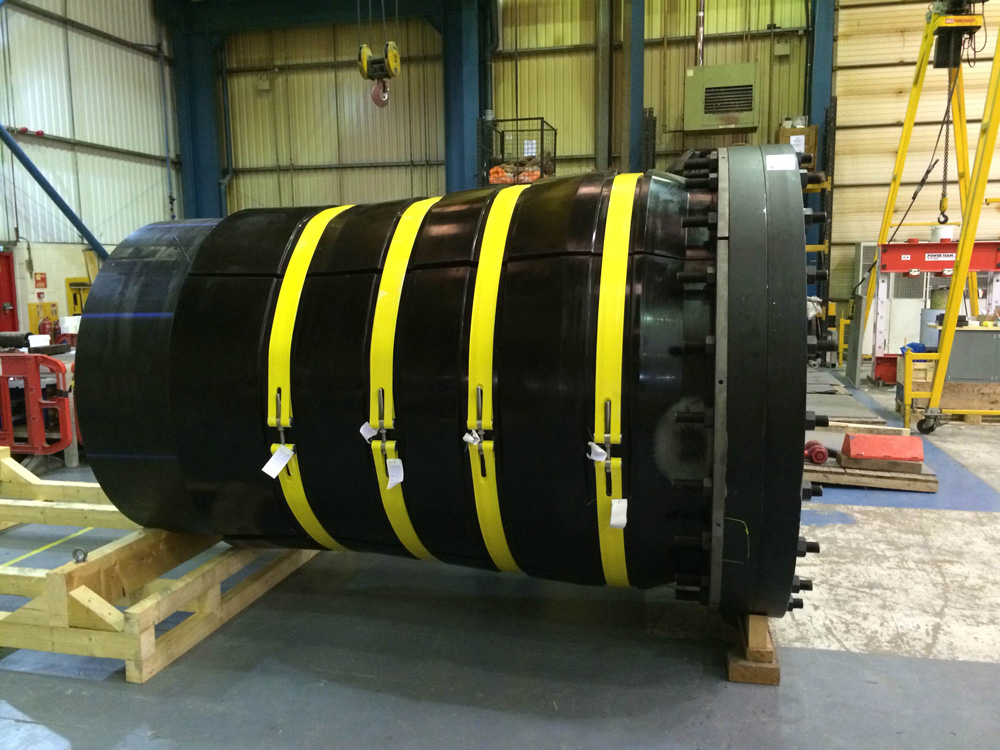
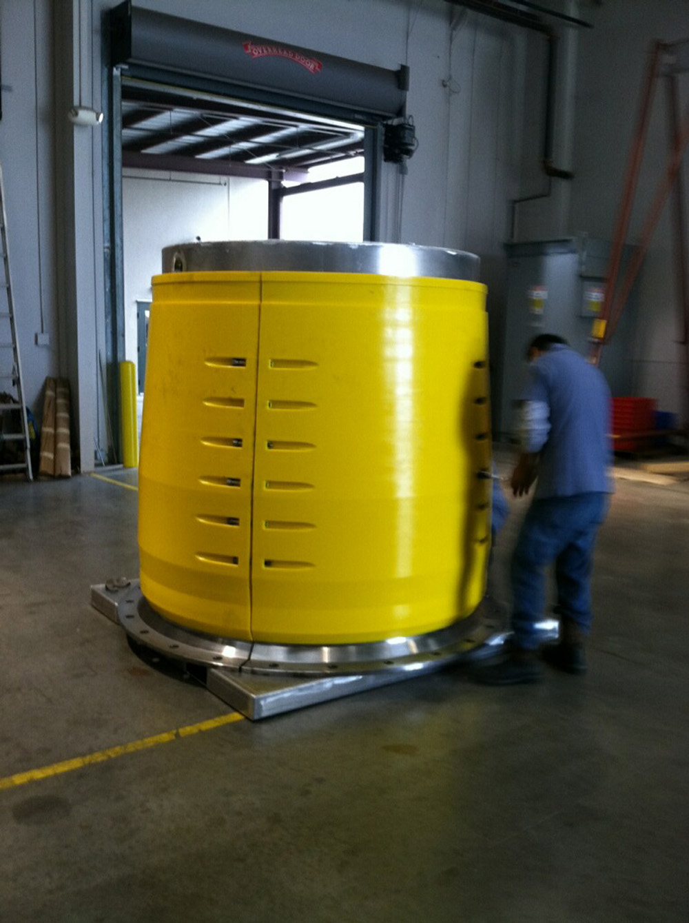

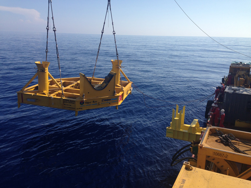
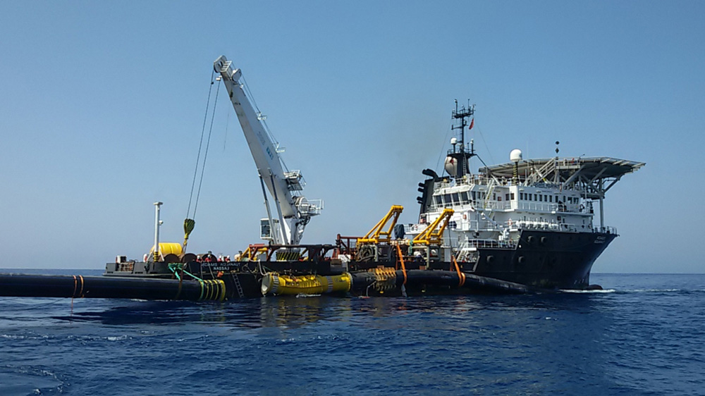
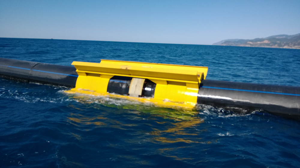
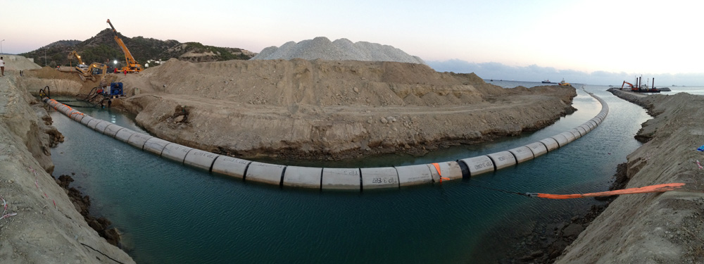
AES was appointed to perform full scale prototype testing on a subsea
steel to HDPE joint solution. The extensive testing program is initiated to
validate the design solution and the supporting analysis to ensure that the 500m
long pipeline components will satisfy the stipulated and inferred requirements,
installation and operational loads.
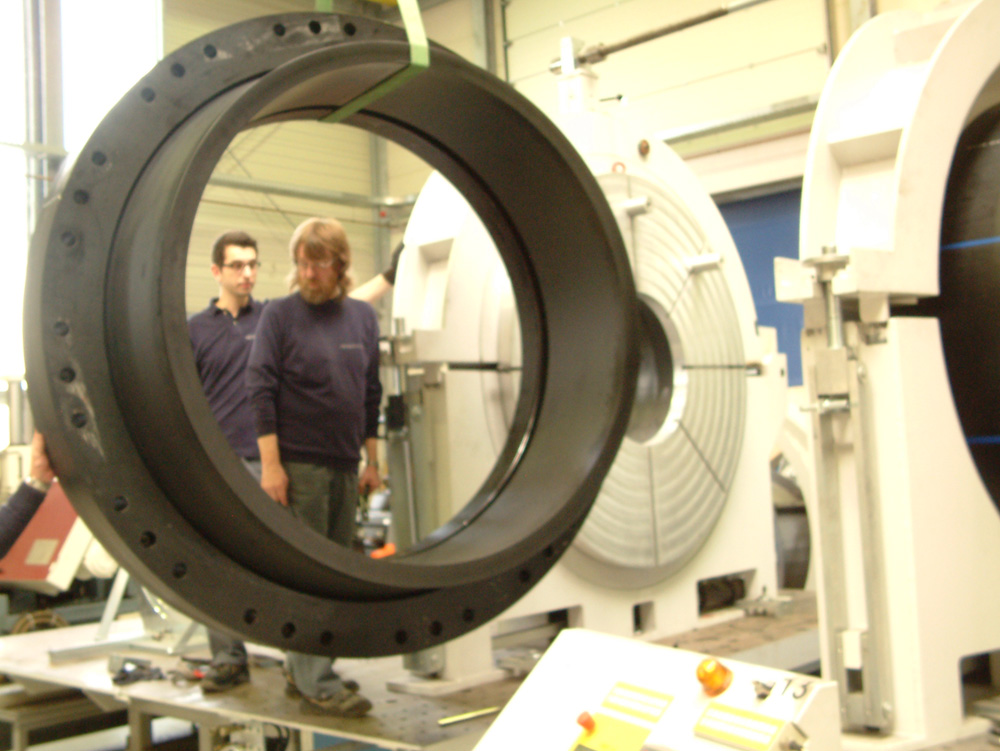
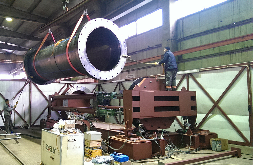
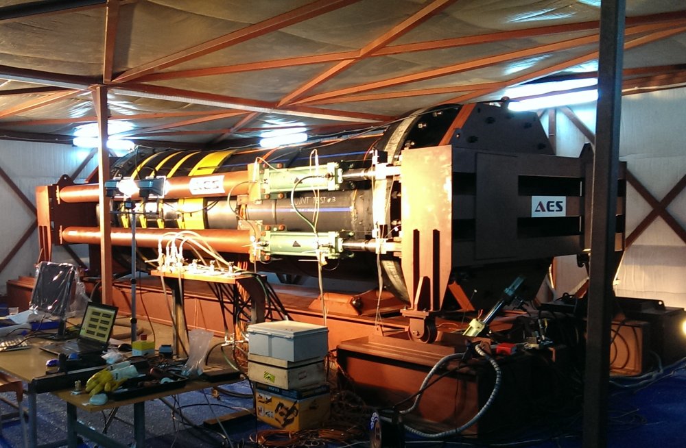
AES designed and delivered a sophisticated test platform to meet the validation objective.
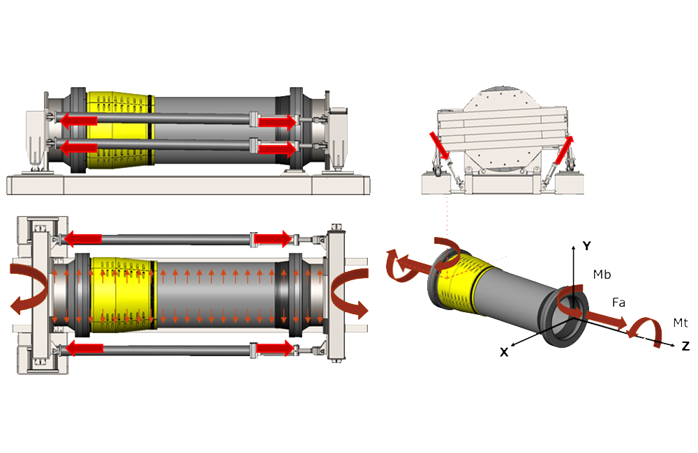
hydraulic test frame
AES team members have been involved with the Program for more than 2 years and delivered a solution to validate the installation and operational pipeline loads.
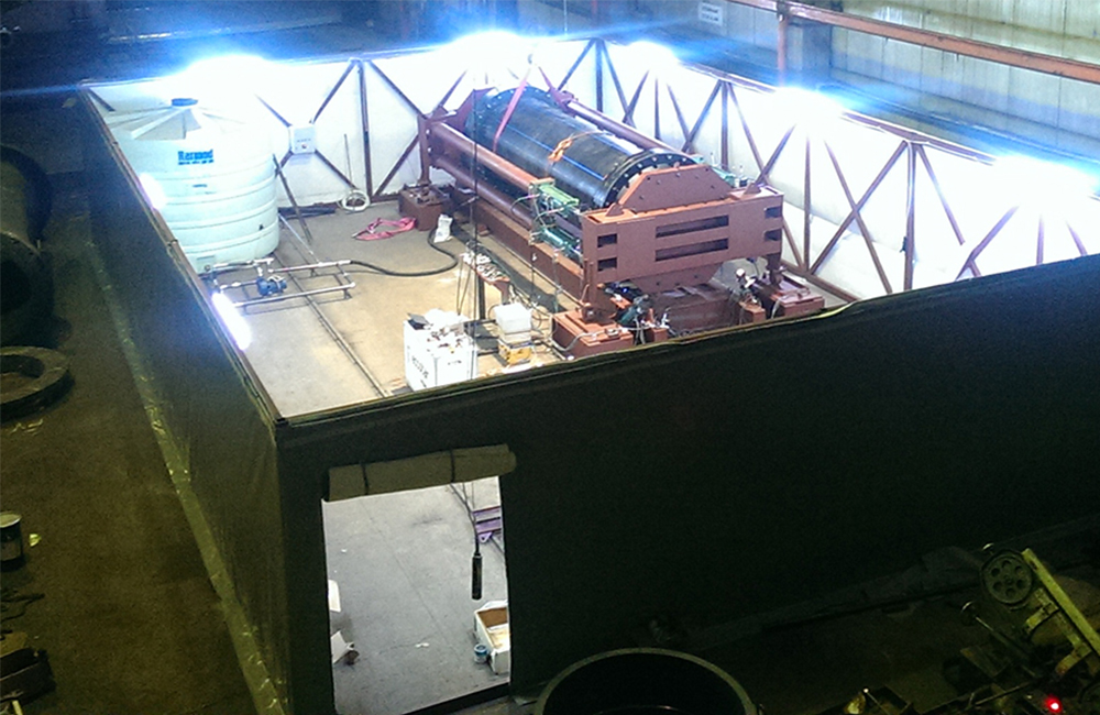
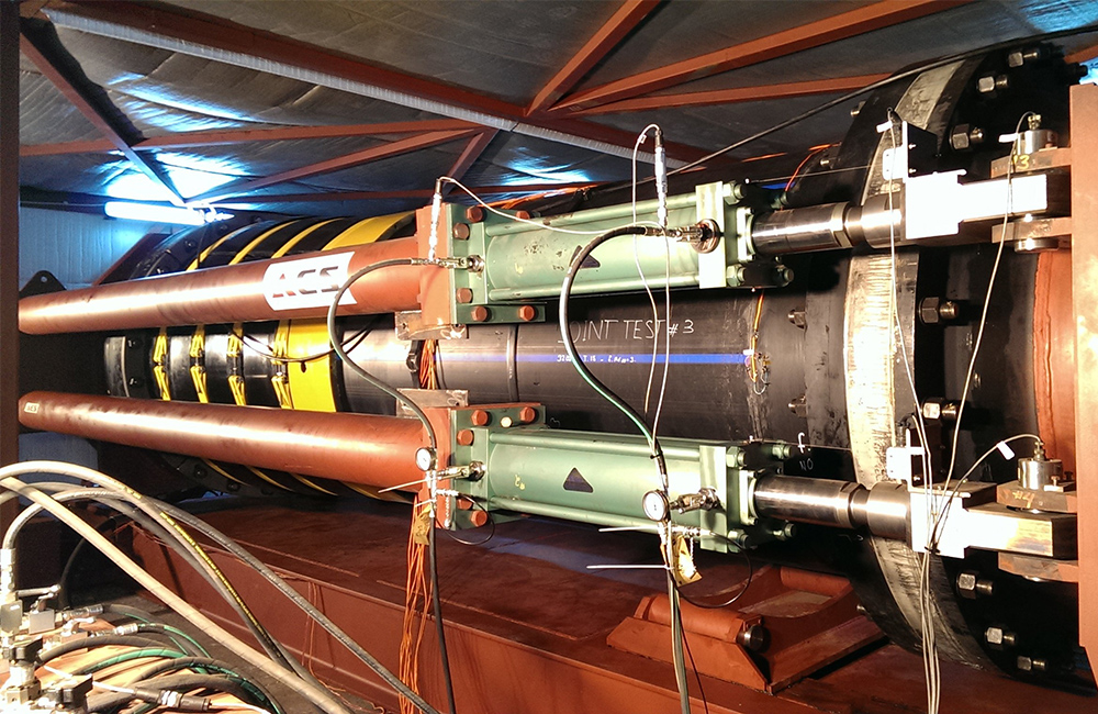
A hydraulic test frame custom designed and built by AES and controlled with a Labview programhas been developed that allows the subsea joint solution to be subjected to various load combinations including tensile loads, moment loads, torsion loads and hydrostatic loads in various magnitudes and axes simultaneously. The test platform proved to be an effective means of performing full scale load testing on pipe line joints and bend stiffener (so called Joint Stiffeners) effectiveness. The test environment is insulated to control the climate and meet the installation and operational temperature specifications during the testing.
Comprehensive testing
program performed to validate:
·
Structural integrity across the connected joint
under installation and operational loads at
·
Characteristics of the pipe and joint at 10C to 15C
design temperature
·
Strain levels at various load combinations
· Seal effectiveness at various load combinations and load levels
· Effectiveness of bend stiffener solution(s)
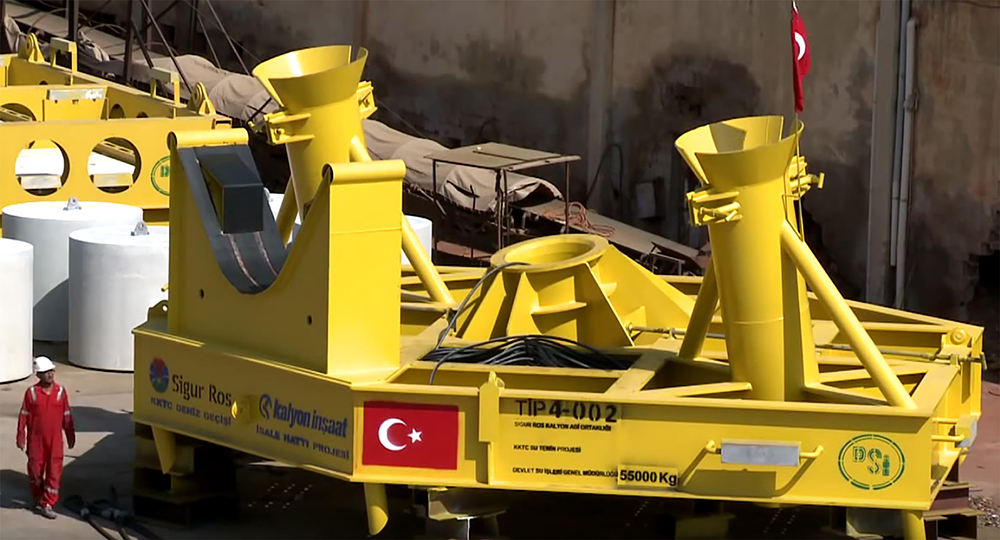
CHALLENGE
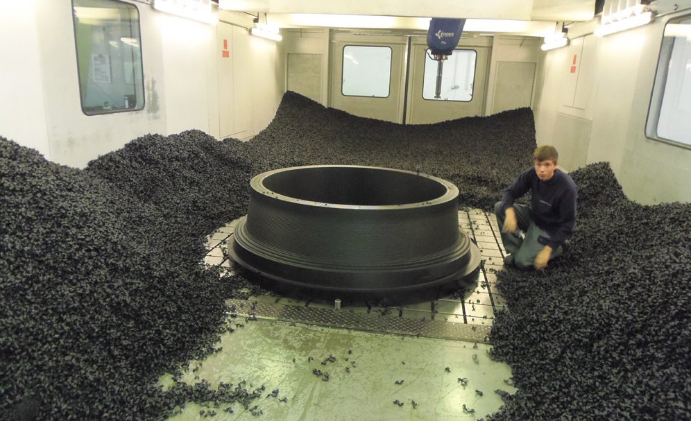
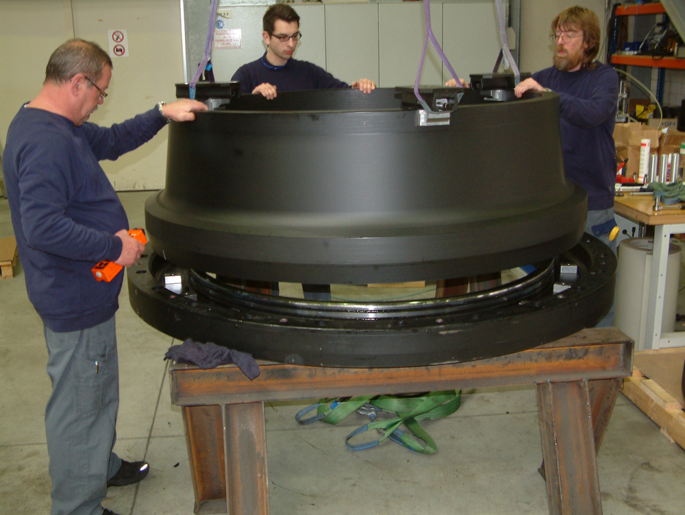
Large full scale prototype test sizes of the joint, magnitude of the
combined loads in multi axes and the constant climate control were the main
challenges to be represented in the testing program. Another key challenge in
the validation was to evaluate to what extent a practical bend stiffener could
be fabricated and used to reduce the nominal stress levels across the pipe
joint region. The distinction was the analytical results based on idealized
form and fit versus a commercial product that can be readily produced and
fitted on PE pipe with fabrication varying tolerances.
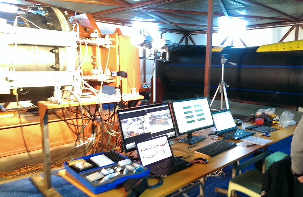
CONTROLS
In order to obtain accurate results, a custom Labview program is developed that is used as a computerized load control center and data recording device to control the loads and record pressure and strain gauge data. National Instruments chassis with appropriate I/O cards and LabView software are used to perform servo control, data filtering, and recording. Clevis load pins are placed in line with the cylinders to provide an independent measurement of the cylinder force.
· Internal pipe pressure
· Ambient and pipe internal water temperature
· Internal pipe pressure
· Cylinder force
o Axial force
o Bending moment
o Torsional moment
· Cylinder displacements
· Strain gauge data (24 units)
· Load pin data
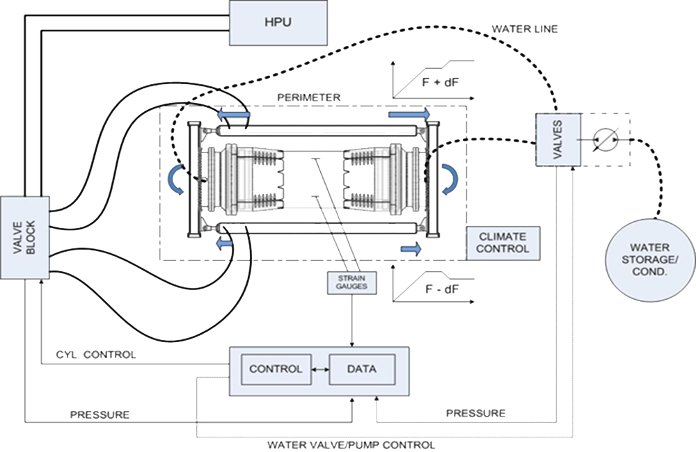
Calibrated and certified clevis pin load cells are used to record each cylinder rod end force for redundancy in force measurement. These clevis load pins are placed in line with the cylinders to provide an independent measurement of the cylinder force. Linear displacement sensors measures the motion of the end plates providing pipe elongation and rotation angles.
Strain gauges are used at predetermined locations based on the analysis results to help validate the analysis methodology, which is the basis for establishing pipeline performance and adequacy of design solution.
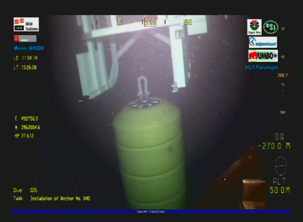
Full scale prototype testing on the 300msw subsea joint completed successfully and the design solution is verified under the witness of ABS Group.